Sensorless FOC using PLL Estimator for PMSM : MCLV-48V-300W and dsPIC33CK256MP508 Motor Control DIM
1. INTRODUCTION
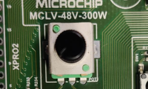
This document describes the setup requirements for driving a Permanent Magnet Synchronous Motor (PMSM) using Sensorless Field Oriented Control (FOC) and PLL Estimator Algorithms on the hardware platform MCLV-48V-300W Inverter Board and dsPIC33CK256MP508 Motor Control Dual In-line Module (DIM).
For details about PLL estimator refer to Microchip application note AN1292 “Sensorless Field Oriented Control (FOC) for a Permanent Magnet Synchronous Motor (PMSM) Using a PLL Estimator and Field Weakening (FW)”
2. SUGGESTED DEMONSTRATION REQUIREMENTS
2.1 Motor Control Application Firmware Required for the Demonstration
To clone or download this application firmware on GitHub,
On the tab <> Code, above the list of files in the right-hand corner, click Code, then from the menu, click Download ZIP or copy the repository URL to clone.
Note:
In this document, hereinafter this firmware package is referred as firmware.
2.2 Software Tools Used for Testing the firmware
MPLAB® X IDE v6.00
DFP: dsPIC33CK-MP_DFP v1.9.228
MPLAB® XC16 Compiler v2.00
MPLAB® X IDE Plugin: X2C-Scope v1.3.3
Note:
The software used for testing the firmware prior to release is listed above. It is recommended to use the version listed above or later versions for building the firmware.
2.3 Hardware Tools Required for the Demonstration
MCLV-48V-300W Inverter Board (EV18H47A)
dsPIC33CK256MP508 Motor Control Dual In-line Module (EV62P66A)
Note:
All items listed under the section Hardware Tools Required for the Demonstration are available at microchip DIRECT
3. HARDWARE SETUP
This section describes hardware setup required for the demonstration.
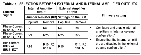
Motor currents are amplified on the MCLV-48V-300W Inverter Board; it can also be amplified by the amplifiers internal to the dsPIC33CK256MP508 on the DIM. The firmware and DIM are configured to sample and convert internal amplifier outputs (‘internal op-amp configuration’) by default to measure the motor currents needed to implement FOC.Table-1 summarizes the resistors to be populated and removed to convert the DIM from ‘internal op-amp configuration’ to ‘external op-amp configuration’ or vice versa.
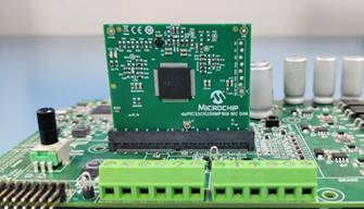
Insert the dsPIC33CK256MP508 Motor Control DIM into the DIM Interface connector J8 on the MCLV-48V-300W Inverter Board. Make sure the DIM is placed correctly and oriented before going ahead.
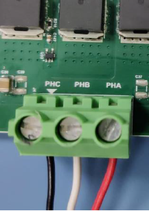
Connect the 3-phase wires from the motor to PHC, PHB, and PHA of the connector J4(no specific order), provided on the MCLV-48V-300W Inverter Board.
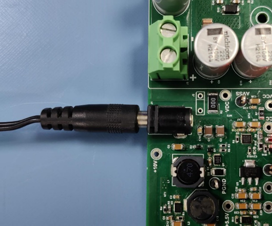
Plug the 24V power supply to connector J1 on the MCLV-48V-300W Inverter Board. Alternatively, the Inverter Board can also be powered through connector J3.
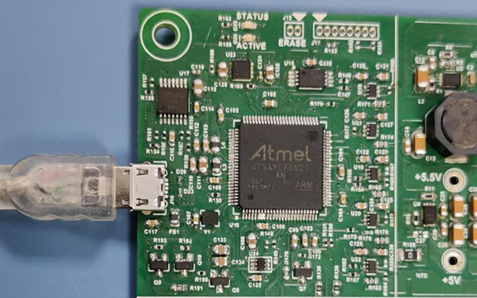
The board has an onboard programmer PICkit™ On Board (PKoBv4) , which can be used for programming or debugging the microcontroller or dsPIC DSC on the DIM. To use the onboard programmer, connect a micro-USB cable between the Host PC and connector J16 on the MCLV-48V-300W Inverter Board.
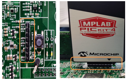
Alternatively, connect the Microchip programmer/debugger MPLAB® PICkit™ 4 In-Circuit Debugger between the Host PC used for programming the device and the ICSP header J9 on the MCLV-48V-300W Inverter Board (as shown). Ensure that PICkit 4 is oriented correctly before proceeding.
4. SOFTWARE SETUP AND RUN
4.1 Setup: MPLAB X IDE and MPLAB XC16 Compiler
Install MPLAB X IDE and MPLAB XC16 Compiler versions that support the device dsPIC33CK256MP508 and PKOBv4. The MPLAB X IDE, MPLAB XC16 Compiler, and X2C-Scope plug-in used for testing the firmware are mentioned in the Motor Control Application Firmware Required for the Demonstration section.
MPLAB XC16 Compiler installation steps, refer link
If MPLAB IDE v8 or earlier is already installed on your computer, then run the MPLAB driver switcher (Installed when MPLAB®X IDE is installed) to switch from MPLAB IDE v8 drivers to MPLAB X IDE drivers. If you have Windows 8 or 10, you must run the MPLAB driver switcher in Administrator Mode. To run the Device Driver Switcher GUI application as administrator, right-click on the executable (or desktop icon) and select Run as Administrator. For more details, refer to the MPLAB X IDE help topic “Before You Begin: Install the USB Device Drivers (For Hardware Tools): USB Driver Installation for Windows Operating Systems.”
4.2 Setup: X2C-SCOPE
X2C-Scope is an MPLAB X IDE plugin that allows developers to interact with an application while it runs. X2C-Scope enables you to read, write, and plot global variables (for motor control) in real-time. It communicates with the target using the UART. To use X2C-Scope, the plugin must be installed. To set up and use X2C-Scope, refer to the instructions provided on the web page.
5. BASIC DEMONSTRATION
5.1 Firmware Description
The firmware version needed for the demonstration is mentioned in the section Motor Control Application Firmware Required for the Demonstration section. This firmware is implemented to work on Microchip’s 16-bit Digital signal controller (dsPIC® DSC) dsPIC33CK256MP508. For more information, see the dsPIC33CK256MP508 Family datasheet (DS70005349).
The Motor Control Demo application uses a push button to start or stop the motor and a potentiometer to vary the speed of the motor. This Motor Control Demo Application configures and uses peripherals like PWM, ADC, UART, etc. For more details, refer to Microchip Application note AN1292, “Sensorless Field Oriented Control (FOC) for a Permanent Magnet Synchronous Motor (PMSM) Using a PLL Estimator and Field Weakening (FW),” available on the Microchip website.
Note:
The project may not build correctly in Windows OS if the Maximum path length of any source file in the project is more than 260 characters. In case the absolute path exceeds or nears the maximum length, do any (or both) of the following:
Shorten the directory name containing the firmware used in this demonstration. If you renamed the directory, consider the new name while reading the instructions provided in the upcoming sections of the document.
Place firmware in a location such that the total path length of each file included in the projects does not exceed the Maximum Path length specified.
Refer to MPLAB X IDE help topic “Path, File, and Folder Name Restrictions” for details.
5.2 Basic Demonstration
Follow the below instructions, step by step, to set up and run the motor control demo application:
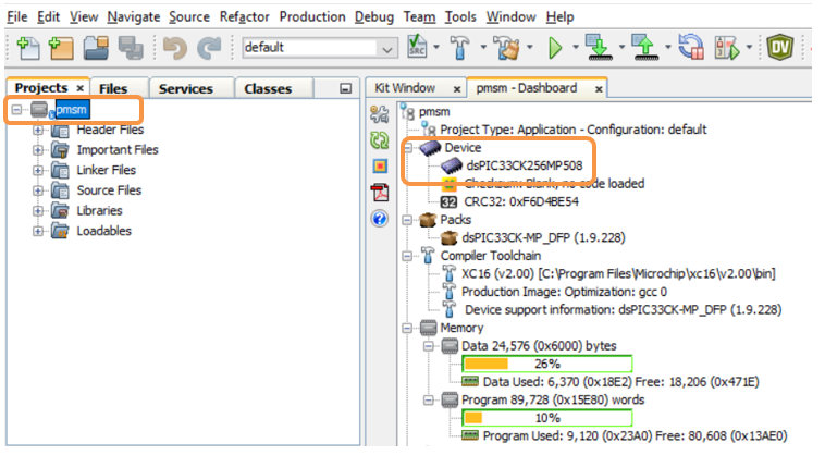
Start MPLAB X IDE and open the project pmsm.X (File > Open Project) with device selection dsPIC33CK256MP508.
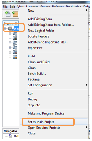
Set the project pmsm.X as the main project by right-clicking on the project name and selecting Set as Main Project as shown. The project pmsm.X will then appear in bold.
Open userparms.h (pmsm.X > Header Files) in the project pmsm.X.
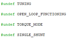
Ensure that the macros TUNING, OPEN_LOOP_FUNCTIONING, TORQUE_MODE, and SINGLE_SHUNT is not defined in the header fileuserparms.h.
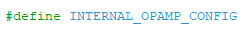
When internal amplifiers are used for current amplification (referred to as internal op-amp configuration), define the macro INTERNAL_OPAMP_CONFIG in userparms.h.
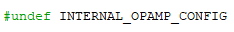
Otherwise, if external amplifiers are used for current amplification (referred to as external op-amp configuration), undefine the macro INTERNAL_OPAMP_CONFIG in the header file userparms.h.
Note:
The motor phase currents can be reconstructed from the DC Bus current by appropriately sampling it during the PWM switching period, called a single-shunt reconstruction algorithm. The firmware can be configured to demonstrate the single shunt reconstruction algorithm by defining the macro SINGLE_SHUNT in the header file userparms.h
For additional information, refer to Microchip application note AN1299, “Single-Shunt Three-Phase Current Reconstruction Algorithm for Sensorless FOC of a PMSM.”
By default, the firmware uses phase currents measured across the phase shunt resistors on two of the half-bridges of the three-phase inverter (‘dual shunt configuration’) to implement FOC.
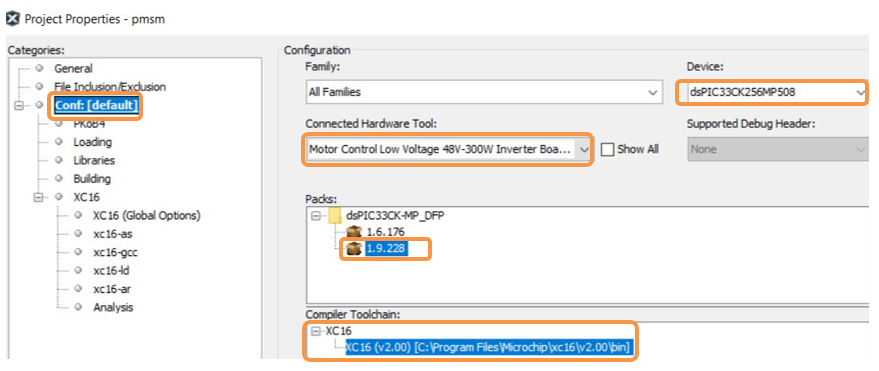
Right-click on the project pmsm.X and select Properties to open its Project Properties Dialog. Click the Conf:[default] category to reveal the general project configuration information. The development tools used for testing the firmware are listed in section 2.2 Software Tools Used for Testing the firmware..
In the Conf:[default] category window:
Ensure the selected Device is dsPIC33CK256MP508.
Select the Connected Hardware Tool to be used for programming and debugging.
Select the specific Device Family Pack (DFP) from the available list of Packs. In this case, dsPIC33CK-MP_DFP 1.9.228 is selected.
Select the specific Compiler Toolchain from the available list of XC16 compilers.
In this case, XC16(v2.00) is selected.
After selecting Hardware Tool and Compiler Toolchain, Device Pack, click the button Apply
Please ensure that the selected MPLAB® XC16 Compiler and Device Pack support the device configured in the firmware
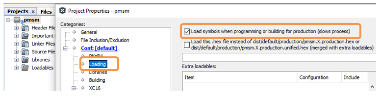
Ensure that the checkbox Load symbols when programming or building for production (slows process) is checked under the Loading category of the Project Properties window.
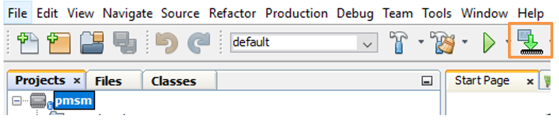
To build the project (in this case, pmsm.X) and program the device dsPIC33CK256MP508, click Make and Program Device Main project on the toolbar
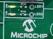
If the device is successfully programmed, LD2 (LED1) will be turned ON, indicating that the dsPIC® DSC is enabled.
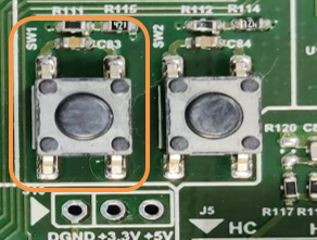
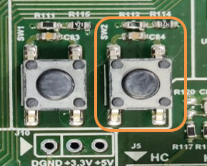
Run or stop the motor by pressing the push button SW1. The motor should start spinning smoothly in one direction in the nominal speed range. Ensure that the motor is spinning smoothly without any vibration. The LED LD3(LED2) is turned ON to show the button is pressed to start the motor.
The motor speed can be varied using the potentiometer (POT1).
Press the push button SW2 to enter the extended speed range (NOMINAL_SPEED_RPM to MAXIMUM_SPEED_RPM).
Press the push button SW2 again to revert the speed of the motor to its nominal speed range (END_SPEED_RPM to NOMINAL_SPEED_RPM).
Press the push button SW1 to stop the motor.
Note:
The macros END_SPEED_RPM, NOMINAL_SPEED_RPM, and MAXIMUM_SPEED_RPM are specified in the header file userparms.h included in the project pmsm.X. The macros NOMINAL_SPEED_RPM and MAXIMUM_SPEED_RPM are defined as per the Motor manufacturer’s specifications. Exceeding manufacture specifications may damage the motor or the board or both.
5.3 Data visualization through X2C-Scope Plug-in of MPLAB X
X2C-Scope is a third-party plug-in in MPLAB X, which helps in real-time diagnostics. The application firmware comes with the initialization needed to interface the controller with the host PC to enable data visualization through the X2C-Scope plug-in. Ensure the X2C-Scope plug-in is installed. For more information on how to set up a plug-in, refer to either the Microchip Developer Help page or the web page.
To establish serial communication with the host PC, connect a micro-USB cable between the host PC and connector J16 on the MCLV-48V-300W Inverter Board. This interface is also used for programming.
Ensure the application is configured and running as described under section 5.2 Basic Demonstration by following steps 1 through 11.
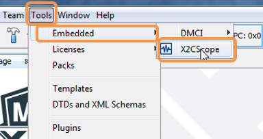
Open the X2C-Scope window by selecting Tools>Embedded>X2CScope.
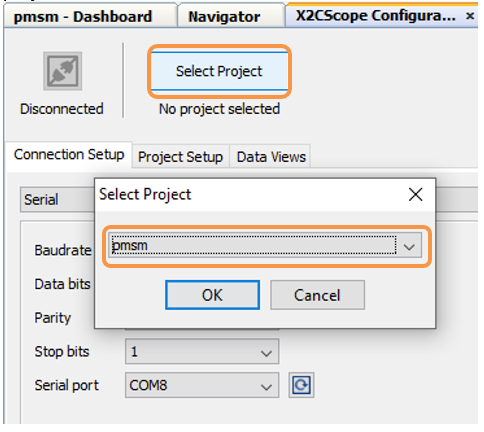
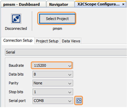
In the X2C-Scope Configuration window, open the Connection Setup tab and click Select Project. This opens the drop-down menu Select Project with a list of opened projects. Select the specific project pmsm from the list of projects and click OK.
To configure and establish the serial communication for X2C-Scope, open the X2CScope Configuration window, click on the Connection Setup tab and:
Set Baudrate as 115200, which is configured in the application firmware.
Click on the Refresh button to refresh and update the list of the available Serial COM ports connected to the Host PC.
Select the specific Serial port detected when interfaced with the MCLV-48V-300W Inverter Board. The Serial port depends on the system settings
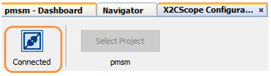
Once the Serial port is detected, click on Disconnected and turn to Connected, to establish serial communication between the Host PC and the board.
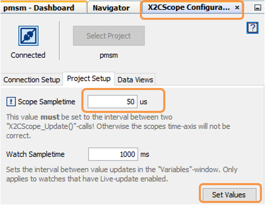
Open the Project Setup tab in the X2CScope Configuration window and,
Set Scope Sampletime as the interval at which X2CScopeUpdate() is called. In this application, it is every 50µs.
Then, click Set Values to save the configuration.
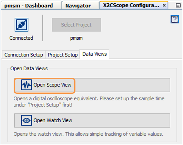
Click on Open Scope View (in the Data Views tab of the X2CScope Configuration Window); this opens Scope Window.
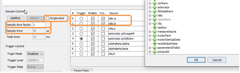
In the Scope Window, select the variables that must be watched. To do this, click on the Source against each channel, and a window Select Variables opens on the screen. From the available list, the required variable can be chosen. Ensure checkboxes Enable and Visible are checked for the variables to be plotted.
To view data plots continuously, uncheck Single-shot. When Single-shot is checked, it captures the data once and stops. The Sample time factor value multiplied by Sample time decides the time difference between any two consecutive data points on the plot.
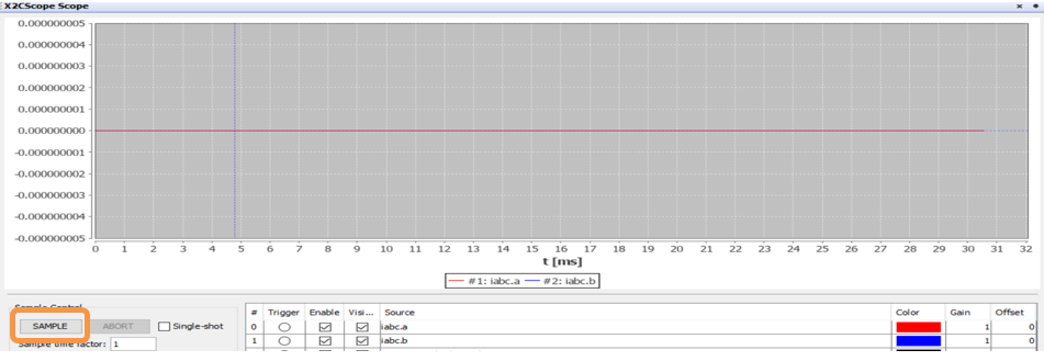
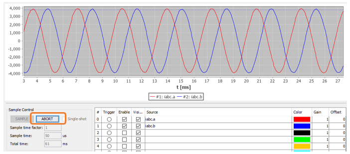
Click on SAMPLE, then the X2C-Scope window plots variables in real-time, which updates automatically.
Click on ABORT to stop.
6. REFERENCES:
For additional information, refer following documents or links.
The Reddit Post Generator is a Python script designed to automatically generate and post content on Reddit. By analyzing trending subreddits and top posts, the script creates innovative posts tailored to maximize engagement and upvotes. It uses OpenAI’s GPT models and LangChain to generate content based on specific rules and summaries.
Features
Automatic Reddit Posting: Posts are generated and submitted to trending subreddits.
Customizable Content Generation: Utilizes various post types such as clickbait, humorous, question-oriented, and more.
Error Handling: Robust error management for posting failures, rate limits, and subreddit restrictions.
Randomized Posting Intervals: Avoids detection of automated behavior by introducing random sleep intervals.
Installation
To set up and use the Reddit Post Generator, follow these steps:
Clone the Repository
git clone https://github.com/feder-cr/reddit_karma_farmer_auto_poster_with_AI.git
cd reddit_karma_farmer_auto_poster_with_AI
Create a Virtual Environment (optional but recommended)
python -m venv venv
source venv/bin/activate   # On Windows use `venv\Scripts\activate`
Install Dependencies
pip install -r requirements.txt
Configuration
To generate Reddit API keys, follow these steps:
Create a Reddit Account:
If you don’t already have a Reddit account, sign up at reddit.com.
Scroll down to “Developed Applications” and click “Create App”.
Fill out the form:
name: Choose a name for your app.
App type: Select “script” for personal use.
description: Optional, add a description of your app.
about url: Leave blank.
permissions: Leave blank.
callback url: Set to http://localhost:8000 (or any URL you prefer for local testing).
permissions: Select read and submit.
Click “Create app”.
Obtain Your API Credentials:
Once created, you’ll be able to see your client_id and client_secret.
Use these credentials in your config_secrets.py file under the Reddit section.
config_secrets.py:
This file contains your sensitive credentials and API keys. It should be placed in the same directory as your main script. Make sure to replace the placeholder values with your actual credentials.
CLIENT_SECRET: Your Reddit application’s client secret.
USERNAME: Your Reddit username.
PASSWORD: Your Reddit account password.
OPENAI_KEY: Your OpenAI API key.
Important: Ensure this file is kept private and not shared or committed to version control to protect your sensitive information.
Usage
To use the Reddit Post Generator, execute the script main.py. Ensure that the configuration files are correctly set up before running the script.
python main.py
Conclusion
The Reddit Post Generator is a powerful tool for automating Reddit content creation. By leveraging AI-driven content generation and automation, users can engage with trending topics and generate content that maximizes interaction.
This project is licensed under the MIT License. See the LICENSE file for details.
Disclaimer
The use of this script for posting on Reddit is subject to Reddit’s API terms of service. The script is provided “as-is” without any warranties or guarantees. For educational and demonstrative purposes only, this script is intended to showcase how Reddit automation might work and is not recommended for real-world use.
Using this script for actual Reddit posting could lead to account suspension or other penalties if it violates Reddit’s guidelines or terms of service. Always use automation responsibly and ensure compliance with Reddit’s rules and policies.
We strongly discourage the use of this script for real-world applications and advise against deploying it for any production or large-scale posting activities.
No distractions. No comments sections. No stylesheets. No JavaScript.
Just an HTML-only Reddit client to stop you entering an internet time vortex.
FAQs
Why did you make this?
I wanted a quick way to check Reddit, stay up-to-date and read interesting things without getting distracted.
If I intentionally want to go down a Reddit rabbithole, I’ll browse it via Libreddit (which is still a lot better than the normal Reddit UI!)
Why is there no CSS or JavaScript?
Why should there be CSS or JavaScript? I think the site works just fine, and it’s a bit of a proof to myself and others that you can make a perfectly functional and usable site using the powers of plain HTML alone.
Are you sure there’s no CSS or JS? Not even a sneaky little style=""?
This means the allowed sources for scripts and styles is 'none', so even if there was any CSS or JS on the page (including via attributes), the browser would refuse to run it!
How/where does this run?
It’s a single no-dependency JavaScript file intended to be deployed via Cloudflare Workers. It should be pretty easy port to any hosting/infrastructure though, as it’s a single JS file that can be easily adapted.
Can I self-host this?
Sure! To host on your own Cloudflare account, just clone the repo, update the details in wrangler.toml, then run wrangler publish in your terminal.
If you want to self-host elsewhere, it shouldn’t be too hard to adapt the JS file, the only things that will need changing is where handleRequest is called from, and possibly the method used to return HTTP responses.
Can I contribute?
Since it’s a fairly small-scale project, I’m not sure how many things there are that need doing! But if you have any ideas or find any bugs, feel free to leave an issue or pull request.
If you enjoy SimpleReddit and want to leave a small tip, you can ☕ buy me a coffee.
Update the apt package index and install packages needed to use the kubectlapt repository. The following steps assume that your apt
package version is 2.3.10 or greater.
This repository presents various projects developed to enhance my skills in dealing with 8-bit microcontrollers such as the ATmega32. It includes implementations of drivers for microcontroller peripherals and some simple applications.
This web app is built upon the TeamMaestro Angular seed.
This web app allows users to directly browse a 4D Database backend and create/edit/delete records. It also provides a 4D Choice List Editor.
Handle with GREAT CARE. The app already validates that user has Admin privileges, but I’d be VERY CAREFUL making this web app available on a production site!MOST SPECIALLY ON A PUBLIC ACCESSIBLE WEB SITE. It is great for development and testing, though.
The distribution folder includes a built version of the FourDAdmin web app. You can download the .zip file in there and copy its contents to a subfolder in your application’s Webfolder. If you have the RESTApi Component installed in your 4D structure, you will be able to browse and edit your database records and choice lists.
There is also an experimental mobile version with basically the same functionality, except for editing records in the database. see
And do not forget to look at additional, more detailed, documentation on the wiki pages.
Browse Table Records
Edit Records
Edit 4D Choice List
It relies on Pascal’s 4D RESTApi being installed on the 4D Database backend.


 https://github.com/RyukieSama/Swifty